單元大綱

    • Keiri Imai, Kenji Oguma, and Koki Sawada, Oshoro-maru Marine Science Department, School of Fisheries Sciences, Hokkaido University


    • By using sound waves, it is possible to quickly and extensively capture what is going on in a large area of the ocean. Sound waves are waves (coarse and dense waves) generated when a vibrating object changes the density of a medium, such as air or water, and the change in density is transmitted through the adjacent medium. Sound that is higher (in frequency) than that which can be heard by our ears (audible sound: 20Hz~20kHz) is especially called ultrasonic sound.

      Sound waves have the characteristic of bouncing back when they hit the boundary of a material, and the bounced sound wave is called an echo (echo). Sonar (Sound Navigation and Ranging) is a device that can detect objects at a distance by determining the distance to the object from the time it takes between the transmission of a sound wave signal and the return of the echo.

      In the old days, depth measurement was done by extending a rope or steel wire from the surface of the water to the seafloor (weight measurement method). With the emergence of the "echo sounding machine" developed by applying sonar technology, the accuracy and efficiency of depth measurement has improved dramatically, and even large depths of several thousand meters can be measured in a matter of seconds. Figure 1 shows a conceptual diagram of an echo sounding machine. Sound waves emitted from a transducer placed near the water surface, such as at the bottom of a ship, propagate through the water and are eventually reflected by the seafloor surface. The echoes reflected back are received, and the distance between the transducer and the seafloor (propagation distance) is calculated by multiplying the time taken from transmission to reception (propagation time) by the speed of sound, and half of this is the water depth. Fish finders, which extend the detection range from the seafloor to fish and other aquatic organisms, are widely used by fishermen as indispensable equipment for efficient fishing.

    • 音響測深機 仕組み

      Figure 1. Outline drawing of Acoustic Bathymetry

      水深:depth 伝搬時間:propagation time 音速:speed of sound

      The speed of sound in seawater varies with water temperature, salinity, and depth (pressure), but is approximately 1,500 m/sec. If the propagation time is 2 seconds, the water depth is calculated as follows.


                                     Depth = 2.0 sec x 1,500 m/sec ÷ 2


                                                = 1,500 m

    • Since echoes contain information about the objects that reflect them, by capturing and analyzing the echoes, it is possible to determine the state of distant locations.By applying this underwater acoustic technology, measurement devices have been developed, such as the "quantitative echo sounder," which estimates the species, size, and number of fish, the "multi-narrow beam echo-sounder," which draws a topographic map of the sea floor, and the "ADCP," which measures the direction and speed of ocean currents.This section introduces these representative acoustic measurement technologies for oceanographic observation.
    • Instruments that measure the movement of an object (speed and direction) using the Doppler effect, which is explained by the phenomenon that the sound of a siren is different when an emergency vehicle is approaching and when it is moving away, are generally called Doppler sonar, and those that measure seawater flow in particular are called Acoustic Doppler Current Profiler(ADCP). Vertical profiles of the flow field in the ocean can be continuously measured by sailing observation using a ship-bottom-mounted ADCP (Figure 2).

    • ADCP

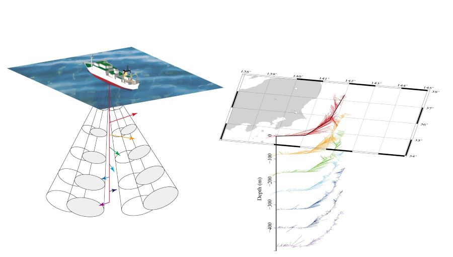
      Figure 2 Tidal current vector diagram obtained by ADCP's sailing observation


    • The basic principle of Doppler sonar is to determine the speed of movement of an object by measuring the amount of change in frequency (Doppler shift) that occurs when sound waves of a certain frequency are transmitted and scattered by a moving object (Figure 3). ADCP transmits sound waves in three or more different directions and measures the movement of multiple layers of seawater in three dimensions by capturing the difference in Doppler shift that occurs when the waves are scattered by particles such as plankton that are moving with the seawater.
    • ADCP 計測原理

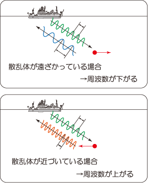
      Figure 3 Outline drawing of Doppler shift

      When the scatterer is moving away → frequency drops

      When the scatterer is approaching → frequency goes up


    • With the emergence of acoustic bathymetry, it became possible to measure bathymetry along a ship's wake. Multi-narrow beam echo-sounder was the next step in the development of "surface" bathymetry. This echo sounding machine is widely used for charting and oceanographic research, and can map the bathymetry of the sea floor while sailing.
    • マルチナロービーム測深機

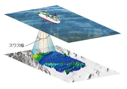
      Figure 4 Bathymetry of Multi-narrow beam echo-sounder

      スワス幅: Swath width


    • Unlike conventional echo sounding machine, which measures the depth at a single point directly below the ship, this machine can simultaneously measure the depth at multiple points spread out in the left and right directions.  By repeating bathymetry while the ship is sailing, the undulations of the seafloor can be depicted in an areal view. The swath width is the horizontal extent of the bathymetry points, and a larger swath width allows a wider area to be measured, while a smaller swath width allows a more detailed depth measurement.

    •       


      Figure 5 Multi-narrow beam echo-sounder observation screen


    • The emergence of Multi-narrow beam echo-sounder has dramatically improved the efficiency of seafloor topographic mapping. Nevertheless, it is not an easy task to survey the vast ocean floor. The area that can be covered in a given voyage schedule is limited, so surveys are repeated over several voyages or by several research ships, and the seafloor is gradually revealed (Figure 6).
    • マルチナロービーム測深機 海底地形図の作成

       Fig. 6 Repeated bathymetric mapping and research voyages


    • Side scanning sonar is a type of sonar that produces three-dimensional images of undulations on the seafloor and is mainly used to research structures such as wrecks and fishing reefs, as well as the topography of the seafloor. An acoustic beam is transmitted obliquely downward from a transducer attached to the ship's bottom or towing structure, and the sound waves that return after hitting the unevenness of the seafloor are received to visualize the undulations of the seafloor. The name "side scan" comes from "Scanning" the "Side" of the transducer.

      With echo sounding machine, which transmits and receives waves from the bottom of a ship, the greater the depth, the longer the time between transmission and reception of echoes becomes, limiting the number of observation points per unit time and resulting in a "coarse" seafloor topographic map. On the other hand, side scanning sonar can transmit and receive waves at a higher frequency by towing the transducer near the seafloor, thus enabling it to capture the undulations of the seafloor in greater detail.


    • サイドスキャンソナー

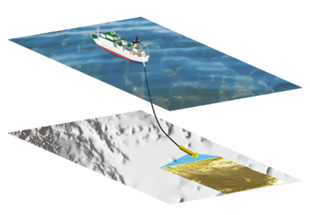
      Figure 7 Towed side scanning sonar observation chart

    • Sound waves are used in stratigraphic exploration for the purpose of searching for seafloor resources, elucidating the mechanism of earthquake occurrence, and conducting preliminary investigations of seafloor civil engineering worksWhen sound waves are irradiated to the seafloor, some of the sound waves that reach the seafloor penetrate below the seafloor surface and are reflected at the boundary between subsurface materials (e.g., the boundary between rocks and subsurface resources). By irradiating sound waves while the ship is moving and capturing the reflected waves from the subsurface, a cross-sectional map of the geological structure can be drawn. In order to penetrate deeper into the formation, sound waves with high penetrability and high energy are used.

      Observation equipment used for stratigraphic exploration includes a "sub-bottom profiler" (Figure 8), which transmits and receives sound waves using a mechanism similar to an echo sounding machine, and a "reflection seismic survey system" (Figure 9), which artificially generates intense very low-frequency sound (seismic waves) by releasing compressed air at once near the sea surface and receives reflected waves using a cable-like sensor deployed on the sea surface.


    • サブボトムプロファイラ

      Figure 8 Sub-bottom profiler - outline drawing


    • 反射法地震探査

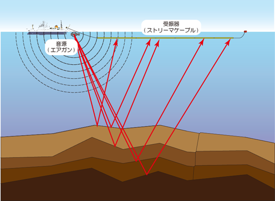
      Figure 9 Refraction seismic survey Observation diagram

      音源(エアガン): Sound Source (Airgun)

      受振器(ストリーマケーブル) : Receiver (streamer cable)


    • Fish finder, which use ultrasonic waves to locate fish in the sea, are widely used in commercial and recreational fisheries. Among fish finders, those that have the ability to quantitatively evaluate the characteristics of fish schools are called quantitative echo sounder, and are used to estimate the amount of marine resources. The measurement results of quantitative echo sounder are output as an image called an "echogram" (Figure 10), which shows the depth and strength of the echoes returned. By using sound waves of multiple frequencies together and analyzing the differences in each echo, an attempt is made to identify the species of fish and their sizes.


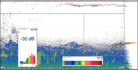
    • Figure 10 Echogram of a quantitative echo sounder


    • While a conventional fish finder can only detect schools of fish directly under the ship, the scanning sonar is an acoustic device that instantly detects schools of fish in all directions by transmitting ultrasonic waves around the entire perimeter of the ship. The detection range can be adjusted to the entire circumference of the ship's bottom by changing the angle (depression angle) of the display section. By detecting schools of fish in the distance and tracking of them in the ocean, you can efficiently catch fish.

    • スキャニングソナー

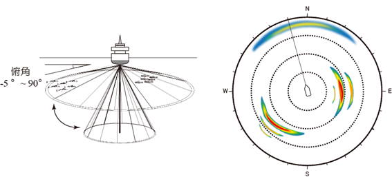
      Figure 11 Scanning sonar detection range and echo display

      俯角: depression


    • Radio waves are actively used for wireless communications in the air, such as cell phones, TV broadcasting, and wireless LAN. Undersea, on the other hand, where radio waves are severely attenuated, acoustic communication technology, which uses sound waves to transmit information, is used for observation. By exchanging information with observation equipment deployed in the ocean via radio waves, it is possible to perform observations beyond the limitations of the method of extending wire ropes and cables from ships. Figure 12 shows some examples of acoustic communication.

      Acoustic signals are used for data communication with observation equipment such as ocean observational equipment moored in the sea or ocean-bottom seismometer installed on the seafloor, and for exchanging command signals when the equipment is recovered (Figure 12-a). Acoustic communication technology is also used to remotely control devices that operate underwater away from the mother ship, such as autonomous unmanned submersibles, and to monitor their measurements and video data without leaving the ship (Figure 12-b). The fishing gear shape measuring device also measures the state of the net during towing (depth, water temperature, slope, state of net opening, towing speed, etc.) with underwater sensors attached to the trawl net, allowing real-time monitoring of the ever-changing state of the net on board the ship. (Figure 12-c).


    • 水中音響通信

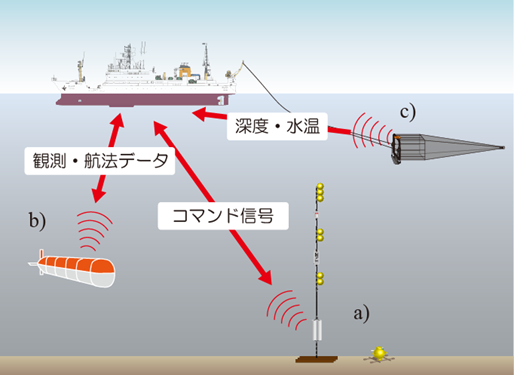
      Figure12 Usage example of underwater acoustic communication

      a) Underwater moored observation equipment  b) Autonomous unmanned submersible c)  Fishing gear shape measuring device

      観測・航法データ: Observation and navigation data

      コマンド信号: Command Signal

      深度・水温: Depth and temperature

    • When collecting sediments with a mud sampler, or when making observations from the water surface to just above the seafloor with a CTD sampling system, etc., it is necessary to know the distance between the seafloor and the instrument (underwater altitude) in order to safely lower the instrument to the vicinity of the seafloor. To do this, an acoustic device (pinger) that emits sound waves at regular intervals underwater is used. The pinger is attached to the instrument or to a wire rope from which the instrument is suspended and lowered together with the instrument. The pinger is attached to the instrument or to a wire rope from which the instrument is suspended and lowered together with the one. The signal (direct wave) emitted by the pinger propagates through the seawater and is received by a transducer on the bottom of the shipThe reflected signal (reflected wave) is received after hitting the seafloor a little later. The difference in the arrival times of these two signals provides the distance between the instrument and the seafloor. The device also sends out pulse signals (pings) at precise time intervals (e.g., once per second), enabling continuous reception and real-time determination of the distance between the instrument and the seafloor (Figure 13).


    • ピンガー 水中高度の計測

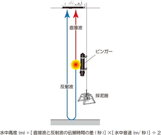
      Figure 13 Conceptual diagram of underwater altitude measurement using a pinger

      反射波: Reflected wave

      直接波: Direct wave

      ピンガー: Pinger

      採泥器: Mud sampler

      Underwater altitude (m) = [Difference in propagation time between direct wave and reflected wave (sec)] × [Underwater sound speed (m/sec)] / 2


  •