
Piston Corer
セクションアウトライン
-
-
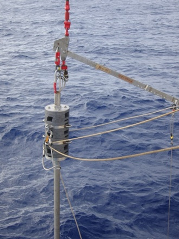
Fig. 1 Piston corer
-
-
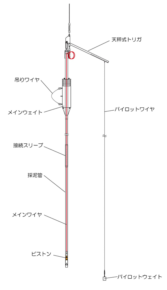
Fig. 2 Schematic diagram of piston corer
吊りワイヤ Suspension Wire
メインウェイト Main Weight
接続スリーブ Connecting Sleeve
採泥管 mud sampler pipe
メインワイヤ Main Wire
ピストン Piston
天秤式トリガ Balance Trigger
パイロットワイヤ Pilot Wire
パイロットウェイト Pilot Weight
-
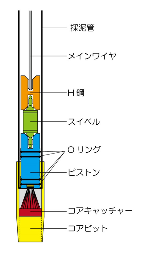
Figure 3 Schematic drawing of the tip of a mud sampler pipe
採泥管 Mud sampler pipe
メインワイヤ Main Wire
H鋼 H Steel
スベイル Sveil
Oリング O-ring
ピストン Piston
コアキャッチャー Core catcher
コアビット Core bits
-
-
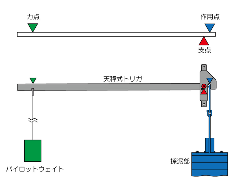
Fig. 4: Balance trigger mechanism (1)
力点 point of effort
作用点 Point of load
支点 fulcrum
天秤式トリガ Balance trigger
パイロットウェイト Pilot weight
採泥部 Mud Collecting Section -
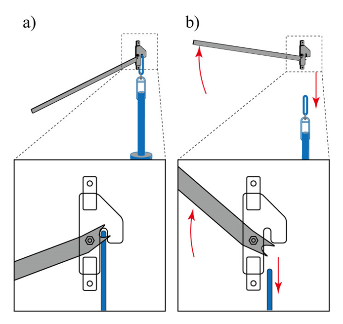
Fig. 5 Mechanism of the balance trigger (2)
a) State before trigger activation b) State when trigger is activated
-
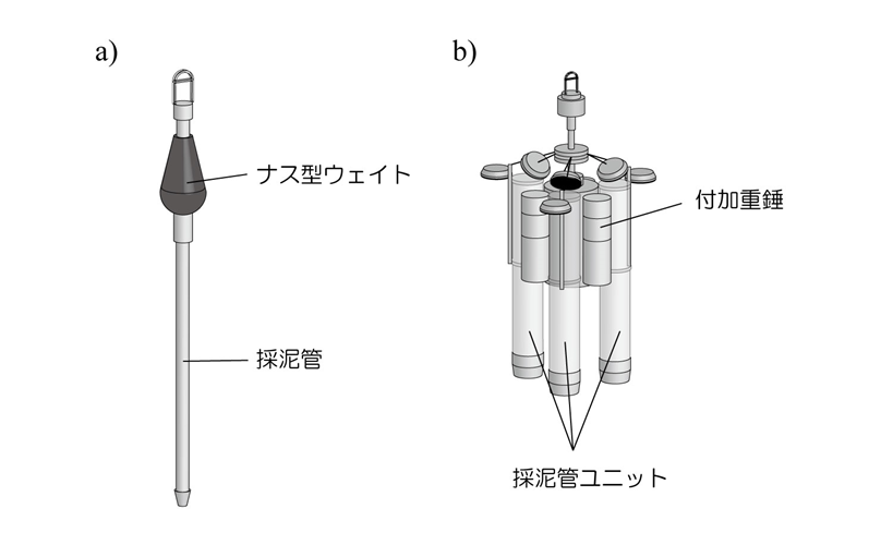
Figure 6 Pilot corer
a) Frager corer
b) Ashlar corer (G.S. type surface corer)
ナス型ウェイト Eggplant type weights
採泥管 Mud sampling pipe
付加重錘 Additional Weights
採泥管ユニット Mud sampling pipe unit
-
-
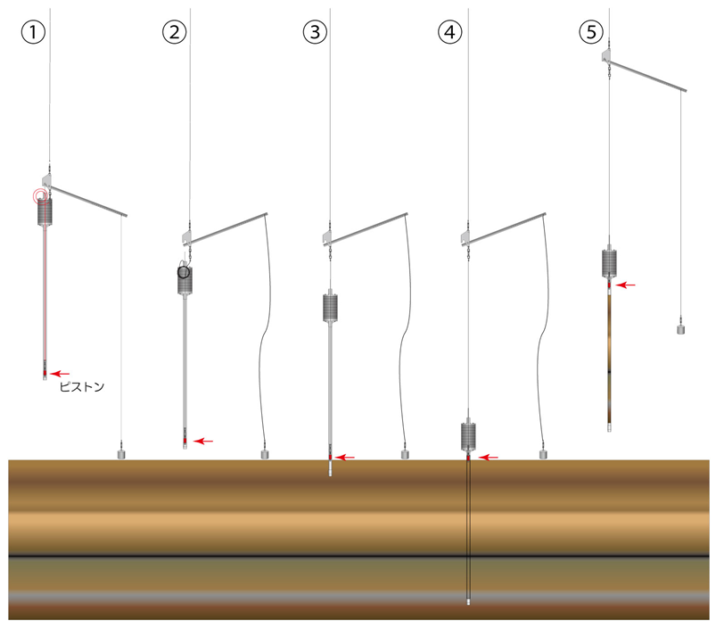
Fig. 7 Piston corer operation (1)
-
Fig. 8 Piston corer operation (2)
-
Figure 9 Comparison of piston corer and gravity corer
a) Gravity corer b) Piston corer
-
-
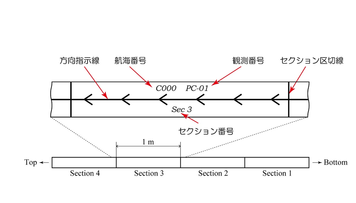
Fig. 10 Example of marking on inner tube
方向指示線 Direction Line
航海番号 Voyage Number
セクション番号 Section Number
観測番号 Observation Number
セクション区切線 Section Separation Line -
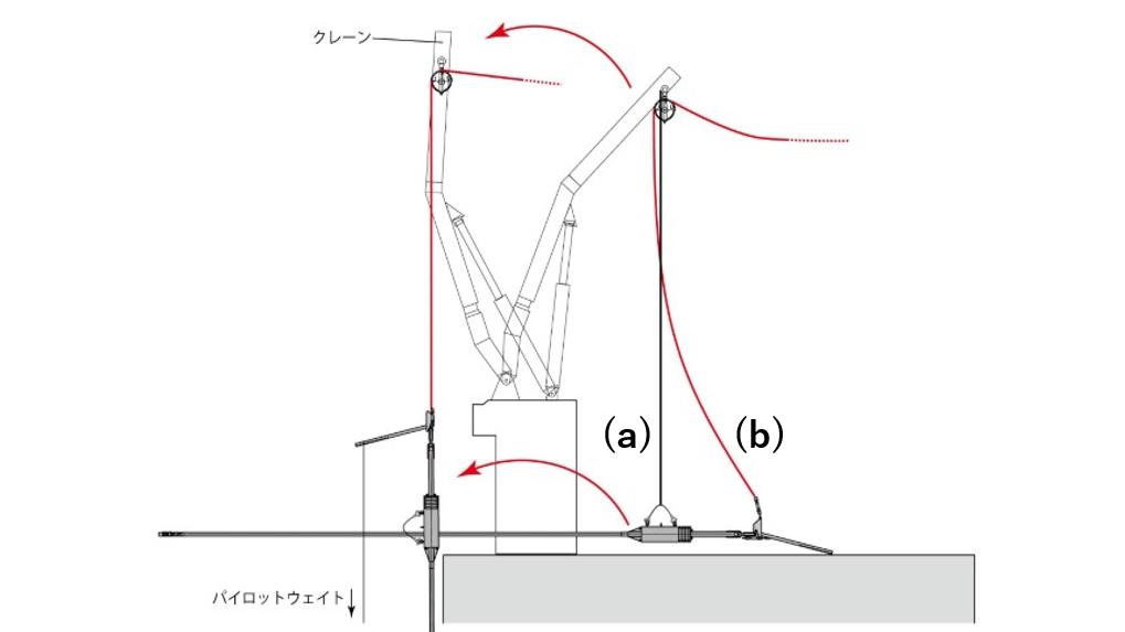
Fig.11 Loading operation of bottom sampler (1)
クレーン Cranes
パイロットウェイト Pilot weight -
Fig.12 Loading operation of bottom sampler (2)
寝かせた状態から From a lying position
だんだんと立ち上がり Gradually stand up
垂直に吊り下げられる Suspended vertically
-
7
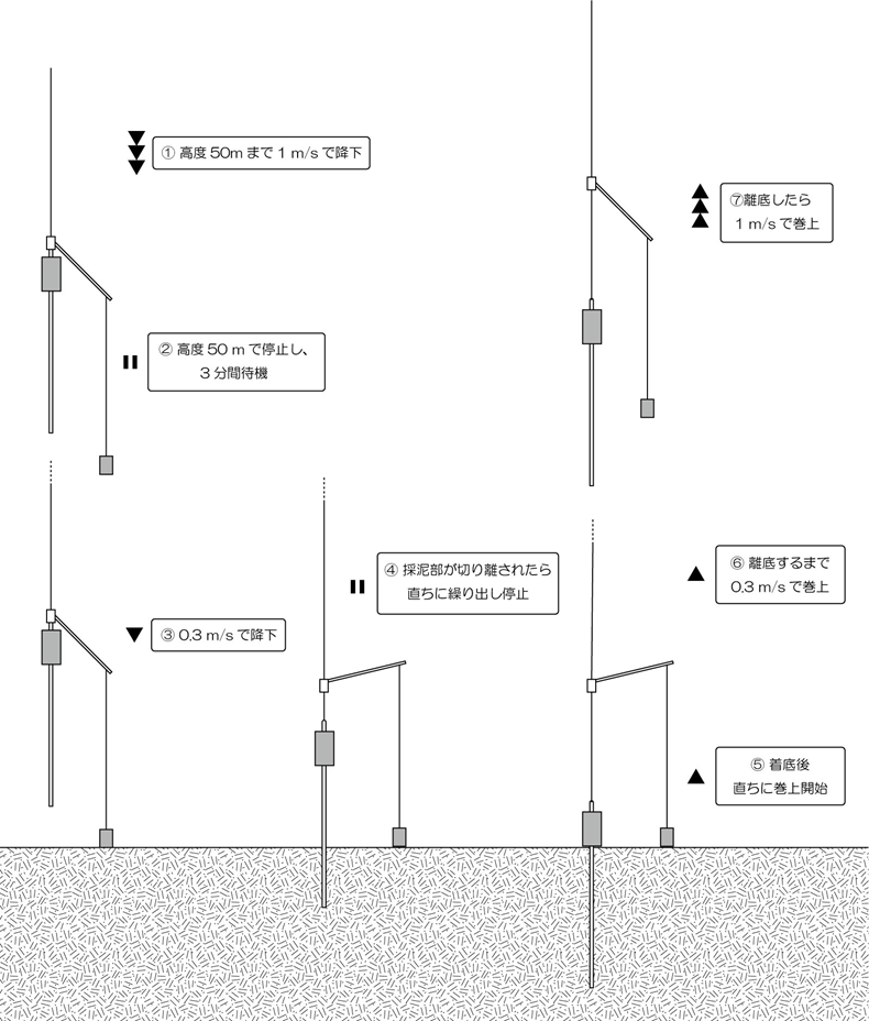
Fig. 13 Winch operation at piston corer landing
1 高度50mまで1m/sで降下 Descend at 1 m/s to an altitude of 50 m
2 高度50mで停止し、3分間待機 Stop at 50m altitude and wait for 3 minutes
3 0.3m/sで降下 Descend at 0.3 m/s
4 採泥器が切り離されたら直ちに繰り出し停止 Stop unloading as soon as the bottom sampler is detached
5 着底後直ちに巻き上げ開始 Starts hoisting immediately after landing
6 離陸するまで0.3m/sで巻上 Starts winding up at 0.3m/s until takeoff
7 離底したら1m/sで巻上 After the vessel leaves the bottom, it winds up at 1m/s. -
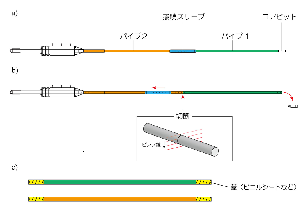
Fig. 14 Sample recovery
a) Condition at the time of lifting b) Cutting off the pipe c) Sealing the pipe
接続スリーブ Connecting Sleeves
コアビット Core Bits
パイプ Pipe
切断 Cutting
ピアノ線 Piano wire
蓋(ビニルシートなど) Lid (e.g., vinyl sheet)
-
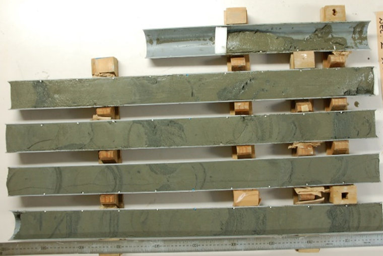
Fig. 15 Semi-split sediment core
-
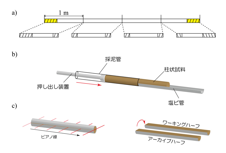
Figure 16. Half-splitting a core
a) Cutting the pipe b) Extruding the core c) Splitting the core in half
押し出し装置 Extruder
採泥管 Mud sampling tube
柱状試料 Pillar sample
塩ビ管 Vinyl chloride pipe
ピアノ線 Piano wire
アーカイブハーフ Archival half
ワーキングハーフ Working half

