章节大纲

    •  In order to obtain high quality samples and experimental data by taking advantage of the performance of the multiple corers, it is necessary to proceed smoothly with the mud sampling operation and quickly process the collected cores for use in experiments after the bottom sampler has been unloaded onboard the vessel. Therefore, each operator must understand in advance the procedures for the work assigned to him or her. It is also important to clarify when and where the samples were collected. In this section, the mud sampling process using a multiple corer is divided into (1) preparation for observation, (2) placing the sample in the sea, (3) landing on the bottom, (4) lifting, (5) collecting the sample, (6) processing the sample, and (7) recording the observation.

    • 1. Preparation for observation

       Attach the mud sampler tube unit, assembled as shown in Figure 7, to the elevating section of the bottom sampler. Open the upper and lower covers of the arm and set it on the trigger. The installation of the mud sampler unit and its setting on the trigger is shown in the video "How to install and set the bottom sampler unit".


    •  

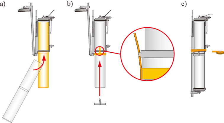
      Fig. 7: How to assemble the mud sampling pipe unit

      a) Pull up the lower cover of the arm and insert the mud sampling pipe.

      b) Insert the latch of the core supporter into the arm and fix the mud sampling tube.

      c) Wrap vinyl tape around the latch to prevent the core supporter from falling off.

    • 2.Putting into the sea

       The bottom sampler is lifted up by the crane, and the wire of the winch is unloaded to put it into the sea. At this time, the stopper fittings installed on the deck to prevent the lifting section from operating are removed. The bottom sampler is held in place with a rope until it is just about ready to be placed in the water to prevent it from swinging in the air due to the ship's motion during these operations. Once the bottom sampler has been submerged to a depth of 50 m, the winch is stopped and a pinger*1 is attached to the wire. The winch is then restarted and the bottom sampler is lowered to the seafloor.


    • 3. Landing on the bottom

       Once the bottom sampler is in the water, follow the procedure shown in Figure 8. The wire is unrolled at a speed of 1 m/sec while checking the underwater altitude of the bottom sampler (distance to the seafloor), relying on the depth of the water, the length of the unrolled wire, and the pinger signal (Figure 8-1). When the bottom sampler reaches 50 m from the seafloor, it stops unloading and waits for 3 minutes to stabilize its position (Figure 8-2). After waiting, the wire is restarted at a low speed (0.3 m/sec) (Figure 8-3). Stop the winch after 30 seconds have elapsed after confirming bottoming (Fig. 8-4). The time when the tension meter*2 detects a decrease in the tension applied to the wire is considered to be the time of bottoming. After landing on the bottom, while the wire is being unloaded, the water hydraulic damper is activated in the elevating section of the bottom sampler to lower and penetrate the mud sampler to the seafloor. If the bottom sediment is sandy, it takes more time for the mud tube to complete penetration, so the winch may wait for several tens of seconds after the winch is stopped. When pulling out the mud sampling pipe, the wire is wound up at a low speed, just as it is done when the pipe is lowered to the bottom (Fig. 8-5). As the wire is wound up, the tension gradually increases, and when a constant tension is observed, the bottom sampler is released. After that, the winding speed is increased and the bottom sampler is quickly retrieved on board (Figure 8-6).

       The bottom sampler must be directly under the vessel so that it does not tilt when it is lowered to the bottom and so that it will not be dragged along after it has been lowered to the bottom. Therefore, the vessel should be maneuvered with consideration of currents and other factors to keep the wire pointing straight down, not only while lowering the bottom sampler, but also from the time it touches the bottom until it is released from the bottom.


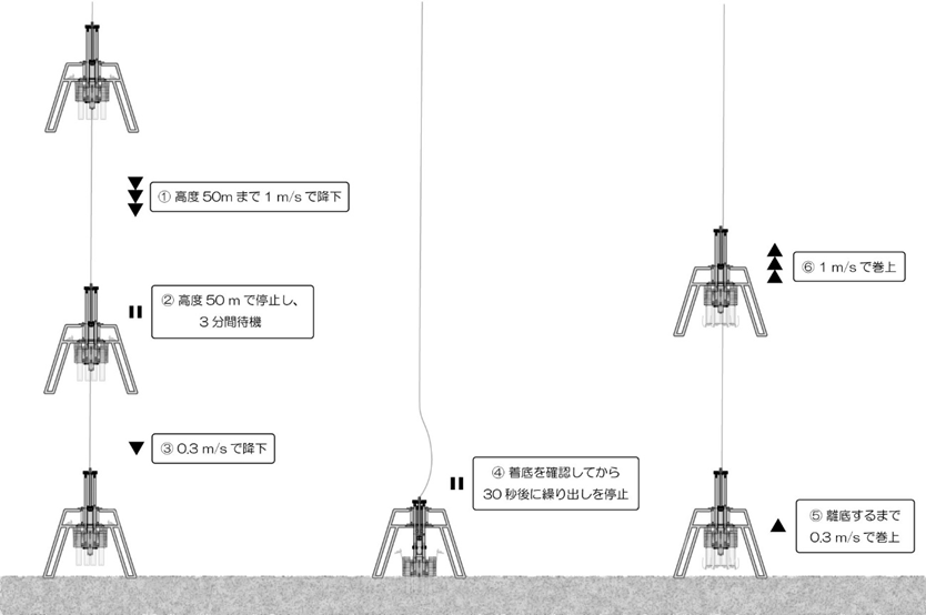
    • Fig. 8 Multiple corer operation near the seafloor

      高度50mまで1 m/sで降下 Descend at 1 m/s to an altitude of 50 m

      高度50mで停止し、3分間待機 Stop at 50 m and wait for 3 minutes

      0.3 m/sで降下 Descend at 0.3 m/s

      着底を確認してから30秒後に繰り出しを停止 Stops unrolling 30 seconds after confirming bottoming

      離底するまで0.3 m/sで巻上 Wind up at 0.3 m/s until the boat leaves the bottom

      1 m/sで巻上 Wind up at 1 m/s

    • 1 Pinger

       An acoustic device that emits sound wave signals at regular intervals and is used to measure seafloor elevation (the distance from the seafloor to the pinger). By using this device to measure the distance between the bottom sampler and the seafloor, it is possible to conduct mud sampling safely and reliably.


      Link:Pinger


      2 Tension meter

       This device measures the tension (weight) applied to the wire. By measuring the increase or decrease of the tension, it is possible to know when the bottom sampler leaves or arrives at the seabed.

    • 4. Lifting

       When the bottom sampler is raised above the surface of the sea, it is moved by crane to the deck, and the stopper is inserted before landing. The bottom sampler suspended in the air may swing greatly due to the impact of waves on the bottom sampler or due to the ship's motion, so as when putting in the bottom sampler, the rope is used to hold it firmly in place while the work is performed. If the bottom sampler comes in contact with the ship's hull or lands on the deck with any impact, the bottom sampler may be damaged or valuable samples may be lost.


    • 5. Sample collection

       After the bottom sampler is lifted, remove the mud sampling tube from the arm. At this time, promptly seal the top and bottom of the mud sampling tube with a stopper. The rubber stopper and spatula shown in Figure 9 are used for this operation. The rubber stopper should be of a size that matches the inner diameter of the mud sampling pipe to be used. First, insert a spatula between the bottom cover of the arm and the mud sampling tube, and open the bottom cover of the arm while pressing the spatula against the underside of the mud sampling tube to prevent leakage of the sample. Next, with the rubber plug pressed against the underside of the mud sampling tube, pull out the spatula and push the rubber plug into the mud sampling tube. Then, after removing the mud sample tube from the arm, the rubber stopper is also placed on the top surface of the mud sample tube. The rubber plugs are secured with vinyl tape to prevent them from falling out when the sample is carried. Careful attention is required to prevent surface sediments from rolling up during these operations.

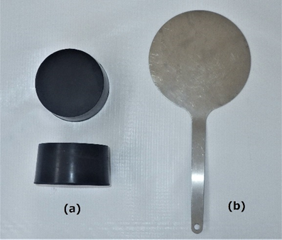
    • Fig. 9 (a) Rubber stopper (b) Spatula

    • 6. sample processing

       The collected sediment samples (cores) are processed according to the purpose of the research. Sometimes the mud tubes themselves are used to conduct experiments on the interaction of sediments with the overlying seawater, while other times the cores are cut into 1- to several-cm pieces and used to study the vertical distribution of material at the sediment surface. This section describes the use of a "core extractor" (Figure 10) to distribute the collected cores by layer.


       The core extractor is an instrument in which a piston that matches the inner diameter of the bottom sampler is fixed on a plate that serves as the base. The piston gradually pushes out the core and separates it into layers. Some core extractors are equipped with an adjuster to precisely adjust the thickness of the extruded core. Figure 10 shows a core remover with an adjuster. This core remover has threads on the outside of the piston shaft and on the inside of the adjuster, which interlock with each other in a "bolt" and "nut" relationship. So, when the adjuster is rotated, the adjuster itself can move up and down along the axis of the piston. In the case of the core remover shown in Figure 10, the adjuster handle is threaded to move downward 4 mm per rotation when turned clockwise. Conversely, turning the handle counterclockwise moves the same distance upward. In other words, turning the handle of the adjuster 2.5 turns clockwise and moving the core extractor 1 cm downward with the lowered adjuster will push out 1 cm of sediment from the top of the core extractor.


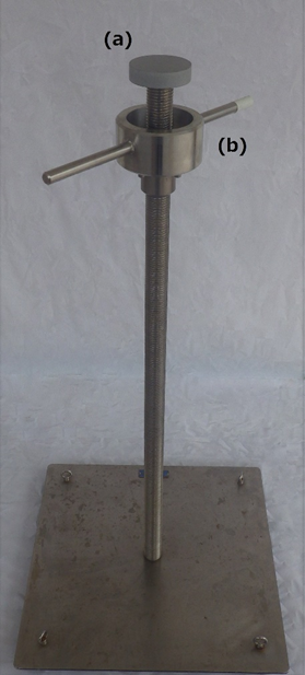
    • Fig. 10 Core remover (a) Piston (b) Adjuster


    •  The sample is cut into pieces using the core extractor in the order shown in Figure 11. The core extraction procedure is described in the order of the numbers in Figure 11. (1) Loosen the rubber stopper on the bottom of the mad sampling pipe, and insert a spatula into the gap between the rubber stopper and the sampling pipe. (2) Place the spatula on the upper part of the piston with the bottom of the mud sampling pipe blocked with the spatula, and then remove the spatula. (3) After pushing the piston into the mud sampling tube, remove the rubber stopper on the upper side. (4), Use a silicon tube or syringe to draw out seawater. This seawater may be separated and used for analysis as seawater directly above. (5) When the mud sampling pipe is pushed down, the sediment is pushed up relatively by the piston. Push down the tube until the surface of the sediment is flush with the top of mud sampling pipe. (6), Turn the handle counterclockwise to raise the adjuster to the bottom surface of the mud sampling pipe. (7) Turn the handle clockwise to lower the adjuster by the desired length, and push down the mud sampling pipe to eject the desired length of sample from the top of the tube. (8) Cut off the extruded sample with a spatula and transfer it into a container. Repeating the process of pushing out the sediment and cutting it off, the samples are cut off in order from the surface layer of the sediment.


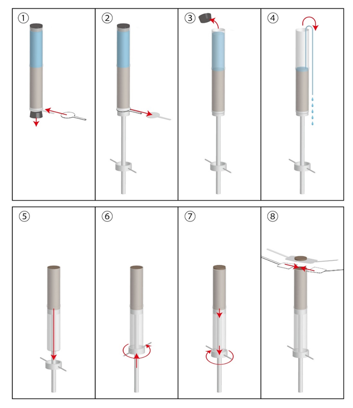
    • Fig. 11 Core removal procedure


    • 7. Observation records

       In mud sampling as well as CTD observation, it is the most basic data and important information for research and survey to record the length of wire unrolled, outline of samples taken, distribution of samples, and destination, in addition to geographical information such as vessel level and water depth at the time of sample collection. Therefore, not a few institutions prepare observation field notebooks specialized for recording the work done when collecting mud.

       Figure 12 shows an example of a fictitious observation result entered in the observation log sheet (Multiple Corer Sampling Log Sheet) used for mud sampling observation using the multiple corer on the Training Ship Oshoro-Maru at Hokkaido University. In this example, two observations are assumed to have been made at observation point "St.3K" on July 7, 2021 during the next voyage of "C000". Before the observation, the name of the station, the date (UTC), and the name of the operator are to be entered. When multiple observations are to be made at the same point, a name is given to the observation operation to avoid confusion in the observation itself and in the handling of the collected samples. Enter the name in the "Sampling Name" column. Also, the information on surface seawater temperature, weather, and time of day are noted in the lower left-hand corner. After that, when the observation work starts, enter the start time and information on the vessel's position at that time (Sampling Start). When the observation proceeds and the bottom sampler touches bottom, the time, ship's position, water depth, and wire information are entered (Bottom touch). The same information is entered when the bottom sampler is returned to the ship (Sampling End). If the wire is pointing straight down during the sampling observation, the sampler is presumed to be directly under the ship, and the ship's position recorded in the "Bottom touch" is presumed to be the position of the seafloor where the sampler touched the bottom and collected mud. On the other hand, wind and currents can change the ship's position and cause it to deviate from the starting position (desired observation point). This can also be confirmed later from the observation logbook.

       Since a maximum of eight cores are collected by the multiple corer, a number (Core No.) is assigned to each one to record under what conditions it was collected. First, check to see if the mud collection tube unit has operated properly. If the upper and lower lids are firmly closed and the mud is collected, enter a "○" in the "Check" column. If the sediment that should have been collected is not collected properly because it has fallen out or the seawater directly above it has escaped through the gap, enter an "×" in the "Check" column. In the "Memo" column, you can describe the condition of the core (e.g., whether benthic organisms were collected, the color of the sediment, whether the seawater immediately above the core is turbid, etc.), how the core was used, and where the samples were taken. In addition, record any special notes about the observation in the "Remarks" column. You may also record information on the bottom sediment in case you wish to repeat the observation at the same location.


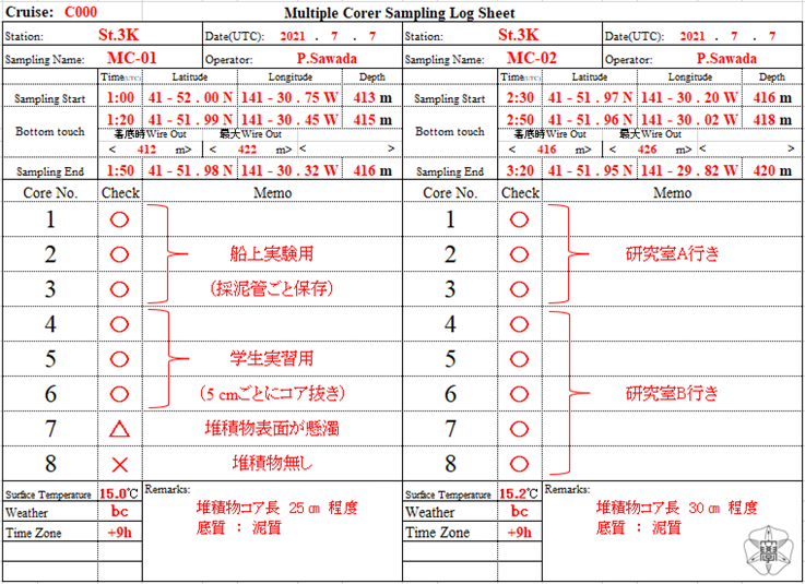
    • Fig. 12 Multiple corer observation field book (example of entry)

      船上実験用 For onboard experiments

      採泥管ごと保存 Preserve the entire mud collection tube

      学生実習用 For student practice

      5cmごとにコア抜き Core extraction every 5 cm

      堆積物表面が懸濁 Sediment surface is in suspension

      堆積物無し No sediment

      堆積物コア長 25cm 程度 Sediment core length: about 25 cm

      底質:泥質 Sediment: Muddy

      研究室A行き To Lab A

      研究室B行き To Lab B

      堆積物コア長 30cm 程度 Sediment core length: about 30 cm

      底質:泥質 Sediment: Muddy